Description
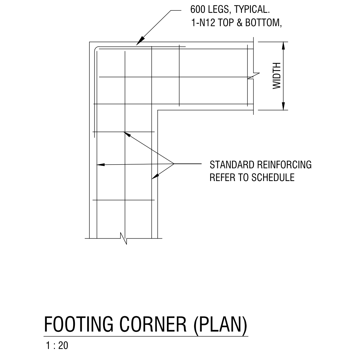
A footing corner detail drawn in plan at 1:20, showing how the reinforcement is lapped and turned where two footing beams meet at a corner. The bars are shown with 600mm legs continued around the corner, an extra 1-N12 top and bottom, and the note refers back to the schedule for the standard reinforcing – the arrangement that keeps the tension steel continuous through the corner so it does not open up under load.
Reinforcing corners correctly is a standard structural requirement, and this annotated plan gives you a ready version to drop into a footing or foundation drawing and size from the engineer’s schedule.
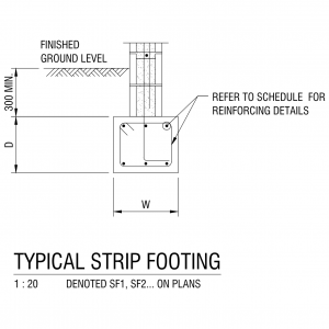
See also the edge and internal footing beam sections and the typical strip footing in the structural details category. A free AutoCAD DWG download.