Description
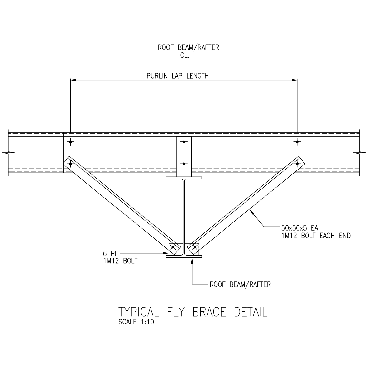
A typical fly brace detail for a steel portal frame, drawn at 1:10, showing how a purlin or girt is braced back to the compression flange of the rafter to restrain it against buckling. The detail sets out a pair of 50 × 50 × 5 equal-angle braces running from the purlin lap down to a 6mm plate welded to the rafter, each fixed with a single M12 bolt at every end, and marks the purlin lap length across the rafter centreline.
Fly bracing is a standard requirement in cold-formed and hot-rolled portal design, and this sheet gives you a clean, annotated version to trace or drop straight into your structural steel drawings – adjust the angle size, bolting and lap to suit your engineer’s specification.
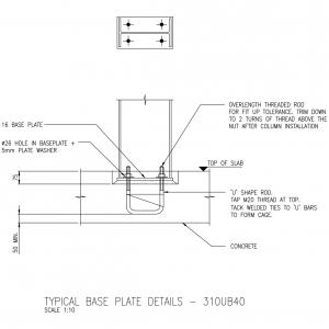
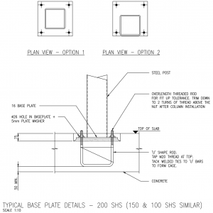
See also the base plate details for 200 SHS and 310UB40 columns in the structural details and steel categories. A free AutoCAD DWG download.